Fire suppression system for main low-voltage switchboards
AeroXFireshield automatically detects and suppresses fire inside the cells, compartments and technical volumes of a main low-voltage switchboard. Protection is sized by zone to account for partitions, width, height, ventilation and hazard location.
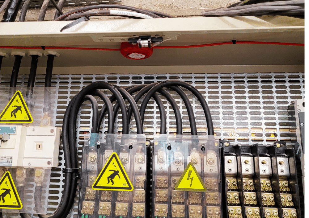
Example of automatic protection for a main switchboard or power cabinet using several AeroXFireshield generators.
Why is a switchboard fire critical?
The main switchboard concentrates supply and distribution for many circuits. Its loss can interrupt all or part of the site and create long replacement delays.
Loss of distribution
One incident can disconnect several areas, workshops or buildings.
Production shutdown
Loss of one cell can stop a complete line or process.
Spread through cables
Conductors and cable routes may carry fire to other equipment.
Replacement lead times
A custom switchboard may take weeks or months to rebuild.
Collateral damage
Smoke, heat and soot may contaminate neighbouring cells.
Business interruption
Downtime cost often greatly exceeds the value of the switchboard.
Where are the hazards inside a main switchboard?
High-power areas, connections and switching equipment are particularly exposed to overheating and electrical faults.
Busbars
Loose joints, oxidation or insulation faults may cause arcing or hot spots.
Power breakers
Switching devices are exposed to strong electrical and mechanical stress.
Cable feeders
Feeder connections may overheat through contact resistance or overload.
Contactors and relays
Repeated cycles and wear can degrade contacts.
Power-factor correction
Capacitors, contactors and protective devices may become fault sources.
Auxiliary transformers
Control supplies and transformers can overheat or degrade.
Dust and pollution
Deposits promote overheating, tracking and ageing.
Ventilation
Ventilation failure increases internal temperature.
A main switchboard is rarely one single volume
Functional separation, metal partitions and separate cells restrict the movement of heat and aerosol.
Why assess each compartment?
- Each cell may have a different volume
- Partitions may block aerosol distribution
- Power and control areas have different hazards
- Doors, openings and ventilation differ by cell
- Detection must follow the actual exposed zones
Sizing consequences
- Calculate each cell volume
- Check maximum width and height per generator
- Allocate sufficient capacity to each zone
- Define generator count and layout
- Choose simultaneous or cascaded activation logic
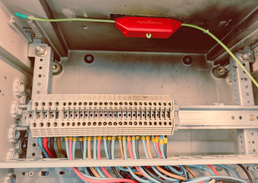
Detect close to the hazard and interrupt combustion in each zone
AeroXFireshield combines linear thermal detection with condensed-aerosol generators distributed according to switchboard architecture.
Monitor critical areas
Heat-sensitive cable follows terminals, feeders, busbars and selected components.
Automatic activation
When the local threshold is reached, the relevant generator or chain activates.
Aerosol distribution
The solid formulation produces active particles inside the protected cell.
Flame interruption
The particles mainly interrupt the chemical reaction sustaining combustion.
Selection depends on each cell, not only total volume
Reliable design combines volume, width, height, depth, partitions, ventilation, obstacles and hazard position.
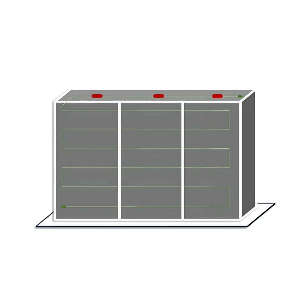
Multiple-generator architecture for a compartmented switchboard
The following layout illustrates distribution logic and is not a universal sizing rule.
Follow power areas without leaving dead zones
A longer cable improves detection coverage but does not increase agent quantity or generator discharge reach.
Above terminals
Place the cable close to connections likely to overheat.
By cell
Each compartment needs a route adapted to its own risks.
Across several levels
An S-shaped route can cover several rows and feeders.
Remote detection
Where the generator cannot align with the hazard, route HDC cable above it.
No obstruction
Heat and flame must not be blocked by equipment or partitions.
No fictitious capacity
Cable length never compensates for excessive width or volume.
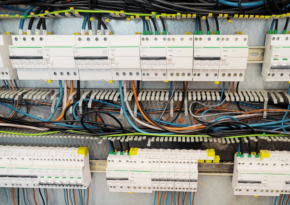
Integrate protection into the site safety scenario
The generator does not directly interrupt power. An interface can control an external device designed and sized for that function.
Activation reporting
Send information to alarm, BMS, building control, fire system or PLC.
Dry contact
Simple interface with a third-party system or technical panel.
Main-breaker command
Possible control of a compatible motorised device.
Contactor command
De-energise a cell or feeder depending on architecture.
Ventilation stop
Possible command to reduce agent loss.
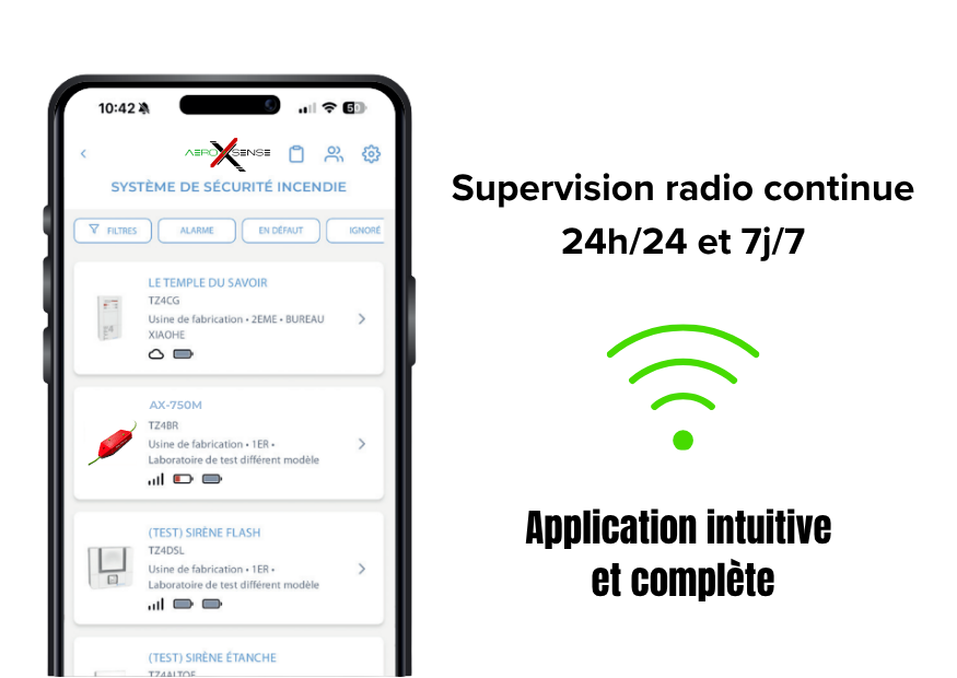
Radio and cloud connectivity
Status reporting and notifications depending on connected versions.
Which approach for each switchboard configuration?
This table provides pre-selection guidance. Final validation must follow the sizing guide and switchboard drawings.
| Configuration | Likely approach | Key consideration |
|---|---|---|
| Small non-compartmented main panel | Pro range | One unit may be possible if volume, width and height comply |
| Compact cell | AX-150M to AX-450M depending on study | Check width, height and equipment density |
| Large power cell | Pro or Industry | Validate capacity and distribution against geometry |
| Multi-cell switchboard | Multiple-generator architecture | One or more units per cell depending on volume |
| Ventilated switchboard | Specific assessment | Consider fan shutdown and suitable margin |
| Several switchboards in one room | Local or electrical-room protection | Compare or combine architectures |
Mistakes to avoid on a switchboard project
Sizing and installation accuracy directly determine protection effectiveness.
Which sites rely on critical main switchboards?
Local protection is especially relevant where power continuity is essential to site operation.
Industry
Production lines, process and critical utilities.
Shopping centres
General distribution for many areas and services.
Hospitals and healthcare
Continuity for technical equipment and essential services.
Data centres
Supply for IT infrastructure and auxiliaries.
Logistics
Warehouses, conveyors, refrigeration and automation.
Hotels and offices
General distribution, HVAC, lifts and services.
Public authorities
Schools, sports facilities and public buildings.
Water treatment
Pumping stations, process and isolated equipment.
Photovoltaic systems
High-power connection and distribution cabinets.
EV charging
Central distribution for several charging points.
Infrastructure
Tunnels, transport, telecoms and technical sites.
Multi-use buildings
Shared switchboards serving several occupants and services.
Build a coherent strategy around the main switchboard
Electrical cabinets
Local protection for power cells and cabinets.
Electrical rooms
Assess whole-room protection for several switchboards.
Sizing
Select models by volume, width, height and compartments.
Interfaces and shutdown
Reporting, dry contact, shutdown command and supervision.
Condensed aerosol
Understand how the extinguishing agent is generated and works.
Professional ranges
Compare Pro and Industry by application.
Photovoltaic systems
Protect PV connection and distribution cabinets.
EV charging
Protect charging panels and distribution cabinets.
Frequently asked questions about main-switchboard fire protection
Comment protéger un TGBT contre l’incendie ?
La prévention associe une conception conforme, une maintenance régulière, la thermographie, le contrôle des serrages et, lorsque le risque le justifie, une détection et une extinction automatiques par cellule ou compartiment.
Quel système d’extinction utiliser pour un TGBT ?
Le choix dépend du volume, de la largeur, de la hauteur, des cloisons, de la ventilation, des obstacles et de la localisation des risques dans chaque cellule.
Faut-il un générateur par cellule ?
Souvent, mais pas systématiquement. Une cellule séparée par des cloisons limitant la diffusion doit généralement être étudiée comme une zone indépendante.
Peut-on protéger les jeux de barres ?
Oui lorsque leur compartiment, leur accessibilité et leur géométrie permettent une détection et une diffusion adaptées.
Comment dimensionner un TGBT compartimenté ?
Chaque cellule doit être mesurée, puis vérifiée selon volume, largeur maximale, hauteur maximale, ventilation et parcours de détection.
Peut-on utiliser un seul gros générateur pour tout le TGBT ?
Pas par défaut. Un volume total compatible ne garantit pas que l’aérosol atteindra toutes les cellules séparées.
Peut-on couper automatiquement le TGBT ?
Une interface peut commander un disjoncteur motorisé, un contacteur ou un autre organe externe, mais le générateur ne coupe pas directement la puissance.
Peut-on renvoyer l’activation vers une GTB ou un SSI ?
Oui selon l’architecture, généralement par contact sec ou module intermédiaire compatible.
Comment protéger un TGBT ventilé ?
Il faut analyser les ventilateurs, les grilles, leur arrêt éventuel et la perte possible d’agent. Une étude spécifique est nécessaire.
Quelle différence entre protéger le TGBT et protéger la salle électrique ?
La protection du TGBT agit dans les cellules. La protection de la salle traite le volume global et les risques situés hors des armoires. Les deux peuvent être complémentaires.
Peut-on installer AeroXFireshield dans un TGBT existant ?
Oui si un emplacement conforme est disponible, que la détection peut couvrir les zones à risque et que l’installation respecte les contraintes du tableau.
Quelle maintenance prévoir ?
Les contrôles visuels, fixations, câble de détection, état du produit et date de remplacement doivent suivre le manuel et le plan de maintenance.
Que faire après une activation ?
Mettre l’installation en sécurité, identifier la cause, inspecter et nettoyer les cellules, remplacer les éléments activés et valider la remise en service.
Un câble de détection plus long augmente-t-il la capacité ?
Non. Il étend uniquement la surveillance. La quantité d’agent et la zone de diffusion restent celles du générateur.
Quelles informations transmettre pour une étude TGBT ?
Plans, dimensions intérieures de chaque cellule, photos, ventilation, schéma unifilaire, équipements présents et besoins de report ou de coupure.
Do you have a main switchboard to protect?
Send drawings, internal cell dimensions, photographs, ventilation, the single-line diagram and reporting or shutdown requirements. We will define the number, capacity and layout of generators.