Photovoltaic inverter fire protection: act directly inside the equipment at risk
The inverter is a central component of a solar installation. It combines power electronics, connections, energy conversion and heat generation. Protection installed directly inside the inverter or its associated enclosure can detect and suppress a fire before it spreads to the room, roof or wider installation.
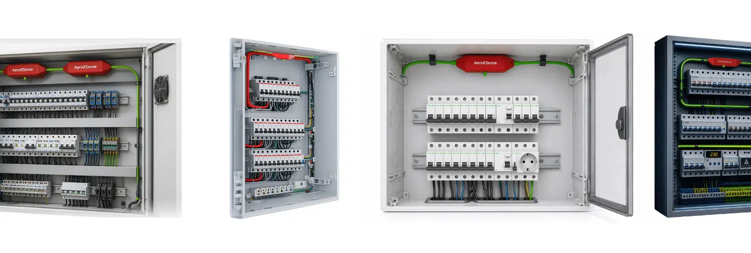
Local protection targets the volume containing power electronics, connections and potential heat sources.
Why can a photovoltaic inverter become a critical point?
Inverters often operate for long periods and undergo major thermal cycles. Environment, ageing and connection quality directly influence the risk level.
DC-side connections
Poor contact, incorrect polarity or degraded connections may cause local overheating.
AC-side connections
Terminals, protection devices and feeders may carry high currents and repeated cycles.
Power electronics
Switching components and capacitors operate under significant thermal stress.
Cooling and filters
A stopped fan or clogged filter reduces inverter cooling.
Insulation fault or arc
Damaged cables or components may create a local electrical fault.
Installation environment
Dust, moisture, heat, insects or poor ventilation may increase risk.
Which photovoltaic equipment should be assessed?
The photovoltaic installation page covers the complete system. This page focuses on the electrical volumes directly involved in energy conversion and distribution.
Central or string inverter
Power electronics, terminals, filters, capacitors and ventilated compartments.
DC combiner box
Isolators, fuses, surge protection, terminals and string grouping.
AC box
Protection devices, contactors, surge protection, metering and outgoing feeder.
Conversion cabinet
Power equipment, controls and communication interfaces.
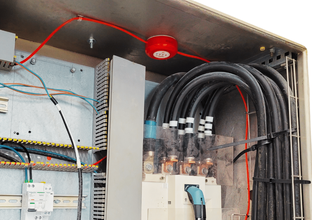
Detect, isolate, contain and report
The sequence must be defined according to inverter type, cooling arrangement and site electrical architecture.
Assess the inverter
Internal dimensions, compartments, ventilation, power, components and location.
Route detection
Heat-sensitive cable follows terminals, boards and exposed power areas.
Coordinate shutdown
The sequence may control ventilation stop or external electrical isolation.
Suppress and report
The generator acts inside the protected volume and the event can be reported.
Monitor several risk areas instead of one point
Temperature does not necessarily rise in the same place in every inverter. Correctly routed linear detection can follow terminals, heat sinks, power electronics and the most critical compartments.
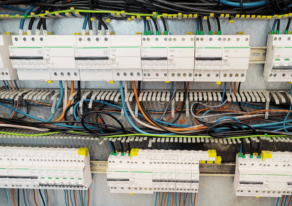
Cable routing is defined according to inverter geometry and the position of risk components.
Volume alone is not enough to protect an inverter
Aerosol distribution must match the actual geometry, obstacles, compartments and airflow.
| Criterion | Question to check | Impact on the solution |
|---|---|---|
| Useful volume | What internal volume is actually accessible? | Determines the minimum extinguishing agent capacity. |
| Compartments | Are boards, terminals and filters separated? | Separate protection or several generators may be required. |
| Ventilation | Do fans continue after detection? | A coordinated shutdown may be needed. |
| Width and obstacles | Can aerosol reach every area? | Distributed positioning and range verification. |
| Operating temperature | What normal temperature is reached during operation? | Detection routing and threshold validation. |
| Maintenance access | Will equipment remain serviceable after installation? | Positioning compatible with inverter maintenance. |
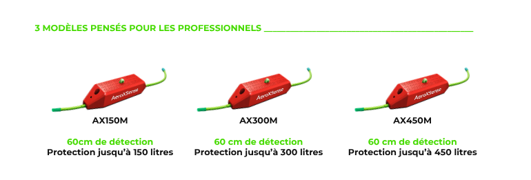
A compact architecture for electrical volumes
Pro and Industry ranges allow capacity, detection length and interfaces to be adapted to the inverter or conversion cabinet.
Compact generator
Installed inside the protected volume without cylinders or pipework.
Heat-sensitive cable
Route adapted to connection and power-electronics areas.
Modular assembly
Several units possible for large or separated volumes.
Safety interfaces
Dry contact, shutdown, ventilation stop or monitoring as required.

Connect suppression to solar plant operation
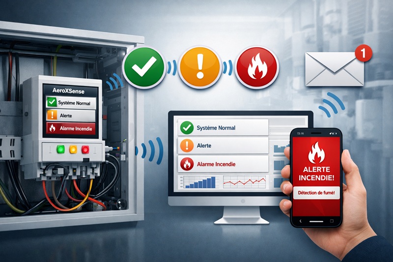
On professional installations, events can be integrated into monitoring systems so teams can intervene and identify the affected equipment quickly.
Status reporting
Information sent to PLC, BMS, SCADA or solar monitoring platform.
Electrical isolation
External command assessed with the AC and DC architecture.
Ventilation stop
Keeps extinguishing agent inside the protected volume.
Connected monitoring
Alerts and data depending on available versions.
Complete your photovoltaic fire protection study
These pages cover the overall system, sizing, electrical cabinets and required interfaces.
Photovoltaic installation
Risks and protection across the complete solar chain.
Electrical cabinets
Fire suppression principles for electrical enclosures.
Sizing
Model selection based on volume, width, compartments and ventilation.
Interfaces
Reporting, shutdown, BMS/SCADA and auxiliary equipment control.
Condensed aerosol
Understand how the extinguishing agent works.
Professional ranges
Pro and Industry models for technical equipment.
Industrial prevention
Integrate protection into a complete risk-control strategy.
Technical contact
Send photos, dimensions and project constraints.
Photovoltaic inverter fire protection: key answers
Why protect the photovoltaic inverter specifically?
Can the system be installed directly inside the inverter?
Does inverter protection replace electrical protection devices?
How is a fire detected inside an inverter?
Must inverter fans be stopped?
Is one generator always sufficient?
Can activation be reported to the photovoltaic monitoring system?
What information is needed for a study?
Do you need to protect an inverter or photovoltaic fleet?
Send inverter references, dimensions, internal photos, ventilation constraints and shutdown or monitoring requirements. We will propose a suitable architecture.